

All machines, without which our lives would not be so comfortable (whether blenders, strollers, computers, airplanes,...), no matter how complicated they are constructed using mostly only seven basic mechanisms: inclined plane (also wedge and bolts), lever, wheel and axle (shaft), pulley, gear and rack, crankshaft and ratchet. Machines are used, for example, to reduce the power needed to perform a job, to speed up work, to change the direction of force, or to change one type of movement to another. In general, we distinguish three types of motion for simple machines (the whole machine or its part):
• linear motion (one-way motion),
• rotate motion (move them into a circle),
• and reciprocating (back and forth).
When using simple machines, especially while using an inclined plane, it is often not a reduction in work. This is a reduction in performance that we must spend. As we climb up the winding roads, it is easier than on a steep road, but performance takes longer. We will explain the efficiency of using the inclined plane in the example. If we pull a 50 kg load to a height of 5 meters on a 10 meter inclined plane, we use the half power we would need to pull this load straight up. However, lower power is spent for a longer time, but we did the same work.
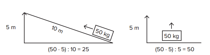
In both cases, we are able to perform the operation. However, if we pull a load on an inclined plane , it is relatively easier, but the work takes longer time. If we take this as a criterion for facilitating work, then the inclined plane makes work easier for us. Probably also because the very heavy load exhausts the muscles very quickly.
The wedges can be understood as two inclined planes placed opposite to each other. Although the direct use of this principle is not so common and occurs only in specific sectors (splitting wood by wedge), in fact, the principle is used quite often, for example in aerodynamics. It is an area that deals with the analysis of the penetration of objects in liquids (in the air, in water). Here too, it is about achieving better performance by using the same amount of power. New car designs are tested in the current chamber to see how the car can penetrate the air. The wider the shape, the lighter the car penetrates through the air, and the power of the engine is more effectively used to move forward (i.e., through the air). We find wedges where we need to more easily penetrate into material, whether gaseous, liquid or solid. The principle of the wedge uses, for example, a knife, a paper cutter, a pencil sharpener, needles, knitting needles, and nails. The basic principle of the inclined plane is also used by a screw that is preferably used (similar to a wedge) for easier penetration into the material. In addition, the wedge can also be used to secure objects against movement, for example, a door wedge latch. Different clamps, nails and clips can also use the wedge principle, while they are used to secure objects, but in principle, through the inclined plane, they penetrate the object. In contrast to the wedge, however, the coiled inclined plane has a wider use as a screw.
The screw is in principle a screwed plane. Allows to move from the bottom upwards by rotating motion. The advantage is that it takes less horizontal space compared to the classic inclined plane. In addition to the classic use of the screw to fix two materials together, the bolt principle is used, for example, in the construction of spiral staircases, serpentine roads in hills, vices, adjustable height chairs, adjustable French keys, threaded lids in cups and bottles, in bulb holders, drills, taps, but also in ballpoint pens. Sometimes the bolt is used less typically, such as a propeller or turbine. By moving the screw in the fluid (gas or liquid) it is possible to move the object forward. In other cases, the screw is immersed in water and is rotated to pump where it is used. Such pumps are often used on irrigation or drainage farms. Specially designed screws can carry solid, liquid and gaseous substances from one location to another. When it comes to solid material, we usually talk about drills, when it comes to liquids, we talk about pumps. When we use a screw to lift objects, it makes it easier to work out of all the simple mechanisms used. Even a very weak person can lift a car using a screw-operated jack. Similar to the inclined plane, the amount of work done here extends over a longer distance – the jack lifts the car very slowly, in small pieces. The denser the thread, the less we work with the jack. The same principle applies when drilling wood screws (or other material). While pulling the screw once around its own axis, it is cut into the wood just a little bit, exactly the distance between the two threads on the screw. This means that the thicker the thread, the easier it is to attract, even if it takes longer. As a result, screws that are easier to attract are usually used in harder wood – those that have a smaller pitch. This pitch is called thread pitch. If we take two screws of the same length but different thread pitch, we can see that the screws differ in the number of turns on the same screw length. Taking the two different spiral staircases we want to climb to the same height, we find that on one staircase the climb is more difficult on the one on which the stairs are higher, and on this staircase we turn less about the stair axis.
Screws are used for joining wood (and similar materials) as well as metal. Accordingly, we distinguish between self-cutting and metric screws:
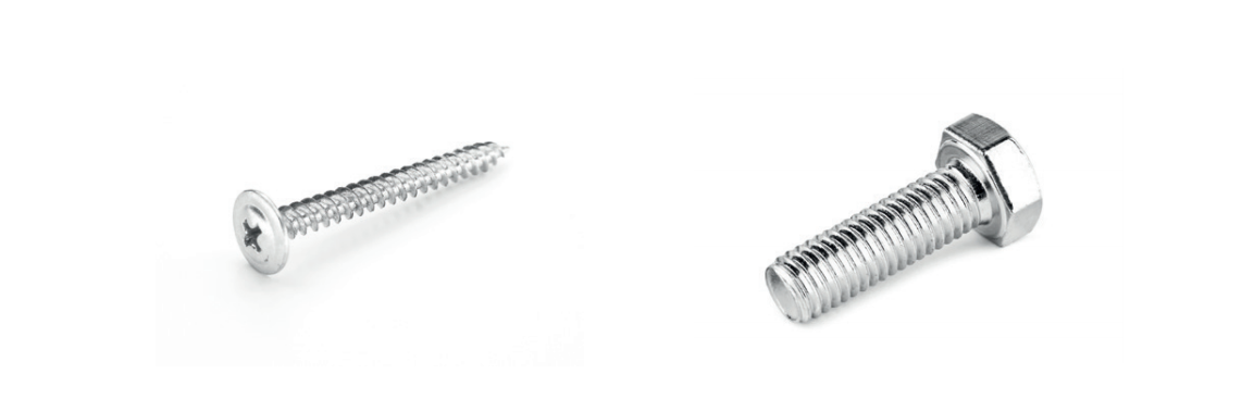
Pic 29: Self-cutting screws and metric screws
Self-cutting screws are wood screws – they have a sharp point, larger thread spacing and do not require a nut. They are used by drilling directly into the bonded material using a tool (screwdriver). Metric screws are used in such a way that holes have to be prepared in the material first, into which screws are inserted, which are fixed on the opposite side by a nut (hollow cylinder with internal thread). It is clear that both types of screws operate on the same principle of a simple machine, but they use different properties of bonded materials. It is also interesting to use tools that move the screw in the material. These are screwdrivers that work on the lever principle. The thicker the handle is, the easier it is to work with the screw.
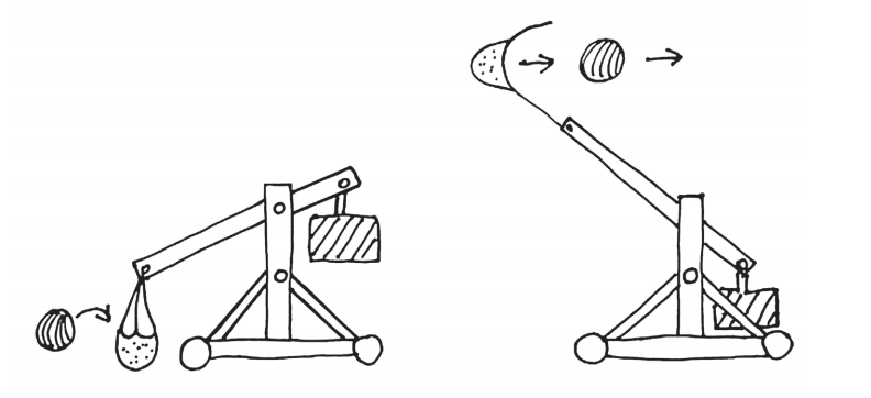
The practical use of the lever has been known since we remember. One of the first thoughtful uses was a catapult (later a more complex trebuchet), which was able to throw stones (later also explosive devices, burning objects, but also bee hives) into the enemy at a relatively long distance.
The lever is used many times without realizing its principal use. For example, the Japanese national judo sport is based on the knowledge that the movement of the entire human body is built on the functioning system of levers. It is also known that a golf player who has longer hands can launch the ball than a player with shorter hands. Similarly, the longer-handed archer can use the same bow to increase the speed of the launched arrow to increase the accuracy of the hit (with optimum aiming).
When using the lever, we distinguish three points – the fixed point, the point of resistance and the point of action of the force. The use of a simple lever has three possible applications. The most used lever is by pushing on a lever that is at a distal part supported by a fixed point and the resistance acts in the same direction, but on the opposite side of the lever (for example, lifting the stone by a rod).

The most used and very popular lever is the swing. It also has three basic points typical for all levers. The fixed point is where the swing rotates; the point of force is where the force actsand the point of resistance is the part on which the load is putted on. If the load is equally large at both ends of the swing, the swing is balanced. Once we want to enjoy swinging it is always necessary to give the same strength to both sides.
For simple levers we distinguish three types of its utilization. Swing, ripper and can openers are a typical example of a first-class lever. In this class, a fixed point is located between the point of application of the force and the point of resistance. If we put two such levers together, we get scissors-like items. By changing the distance of the fixed point from the point of application of force, we also change the force needed to control the resistance, or we can accelerate the movement at the end of the lever by relatively slow motion on the force side. This type of lever even changes the direction of movement. For example, we press the scissors in the opposite direction to the direction in which the individual blades move. However, if the distance between the point of resistance and the point of application of the force is the same, such a lever can only change the direction of action of the force. The necessary force is not reduced and the movement of the object is not accelerated (eg swing). Based on this principle, it is possible to explain why the scissors cut a thick paper lighter at a point near a fixed point (a pair of scissor arms) than at the ends of a scissor.
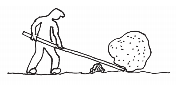
Barrow is a typical example of a second-class lever. An example of a double lever of this class is a nutcracker for nuts. The fixed point is located at the beginning of the lever. Resistance acts close to a fixed point and we have to act on the opposite end of the lever against the effect of resistance. It‘s as if we wanted to roll a stone out of the way with a stick. The longer the rod, the easier it will be; the longer the nutcracker shoulders, the easier the nut to crack.
The third class of lever is the location of a fixed point on the edge of the lever, the force acting in the vicinity of a fixed point and the resistance acting in the opposite direction at the end of the lever. A typical example is the use of the forearm. If we hold something in hand, it is better to keep it if the elbow rests on the table – a fixed point and we can only lift it by exerting a force with the opposite effect acting on the hand. The closer to a fixed point this force is, the less power we need; we use biceps in the shoulder. Other examples of using a third class lever are tennis racket, rod, broom, flytrap. In this type of lever, the force is exchanged for speed and distance. For example, if a fisherman wants to move the hook on the hook relatively quickly, he can only do so with a very slight movement of the hook in his hand. The double lever of this class is used, for example, for tweezers, sugar tongs.
The wheel has always been considered the greatest discovery of human history. In fact, however, it would have almost no use without being connected to the axis. The axis is a stick or rod that passes through the center of the wheel and allows the wheel to rotate freely around it. If you rotate the axis, the wheel is also spinning and vice versa. This way we can use the power to move. The wheels are located in all devices that perform rotary motion (but not only in them), such as in a hair dryer, car engine, carousel, bicycle, and so on. Gears have specific applications. Gears are wheels that have teeth on the edges at regular intervals. If we engage multiple gears, we can move motion from one wheel to another. If the wheels are unevenly large, we can accelerate or slow down the wheel axis by connecting these wheels.
By placing the jack handle further away from the axis of rotation, we reduce the amount of flowing force required. A larger wheel can be used instead of the jack handle. For example, compared to pencil sharpeners, a meat grinder needs a larger handle to work well with it. This difference can be understood by comparing the distance between the point of application of force and the point of resistance of the force. By the same principle, it is also possible to explain why larger steering wheels spin more easily than smaller ones. The combination of wheel and axle can change their function by using a belt, chain and gears. A bicycle is an example of wheels and axes interconnected by a chain. By being connected using a chain, one turn of a large wheel turns the small wheel several times around its own axis. By converting gears, we can change the speed of movement of parts that are attached to the gears axes. The mechanical advantage of two chain-coupled gears can be calculated by the ratio of the number of teeth at one and the other wheel.
The fixed pulley changes the direction of the acting force. A movable pulley reduces the amount of effort required to pull out the load – simplifies work. As the name implies, the fixed pulley is attached to the stationary object (fixed point) and the movable pulley moves, either vertically or horizontally according to the way it is used.
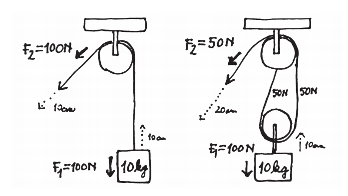
The pulley block is a system of fixed and movable pulleys. The simplest pulley block consists of one fixed and one movable pulley. By adding pulleys, we effectively reducethe effort needed to lift the load. Rubbing string on the pulley Wheel can cause smaller effect of the effort reduction. Friction can be reduced, for example, by oiling friction surfaces. The mechanical advantage of using pulleys can be easily calculated. The pulley with two pulleys makes working two times easier, the pulley with three pulleys makes it easier to work three times and so on.
The pulleys do not have to be used only to facilitate the movement with the load. They are often used to transmit force. For example, small pulleys can spin large pulleys that spin slower, but provide more torque. A typical example of such use is the car engine. The wedge belt is driven by a pulley that is connected to the motor. The wedge belt rotates the water pump to provide water circulation in the radiator, a fan (which blows cool air over the radiator) and an alternator (needed to charge the battery). In the house, the pulley is used, for example, in a washing machine and a clothes dryer for spinning the laundry drum.
The crankshaft is another type of shaft-to-wheel connection and is usually used where the direction of force is to be changed or the reciprocating movement can be changed to rotational. At present, it is used, for example, to transfer rotary motion in a car engine to move back and forth in pistons. The crank is on the spinning wheel usually placed on the edge. By rotating the wheel, the attached crank causes, in a specific design, movement (e.g., piston) back and forth. Similarly, the foot movement changes back and forth on the bicycle pedals to rotate the bicycle wheel. A well-known use of the crankshaft is also a saw. For example, in the past the saw was powered by a water wheel. The spinning water wheel transferred its rotational motion to the wheel on which the crank was mounted. The rotational movement of the wheel changed to the reciprocating motion of the saw back and forth (as on the Picture).

Steam locomotives used the reverse movement of the steam piston back and forth to rotate the wheels. Water heating produced water vapor, which pushed the piston out, causing the wheel to move. In the displaced position of the piston the steam escaped, the piston returned and the event could be repeated cyclically.
Sometimes, when constructing various devices, we need a machine or part of it to move in one direction only, for example, on turnstiles that cannot move back. Usually a ratchet is used in these devices. This is formed by a toothed wheel with a pawl – a lever whose end fits into the teeth of the gear so that, when attempting to reverse the wheel, the pawl prevents rotation. The gearwheel itself has latch teeth adapted (inclined). We also call this gear a ratchet wheel.

Ratchets are also used, for example, in pendulum clocks for gears. By swinging the pendulum back and forth, where we need the clock hands to move in one direction only, we need a latch to ensure that the ratchet does not rotate and the gears attached to it when the pendulum is backward. The ratchet is also used on roller shutters, but also on car safety belts. The seatbelt mechanism is somewhat more complicated, since it is necessary to activate the belt to stop in the impact. Usually a weight is placed on the ratchet. The weight moves forward in a car crash and activates the ratchet. A very well-known use of the ratchet is the ratchet wrench and also the pulling tape. Ratchet teeth are provided over the entire length of the plastic or metal tape, passing a loop through the strip at the end of which there is a ratchet. Tape is used to bind things together.
Many devices operate on a combination of two or more simple machines. Examples of such tools are, for example, scissors. While the blade uses the wedge principle, the scissor arms use the lever principle. The lawn mower uses a combination of wedge (blade), wheel and axle to which the blades are attached. We would certainly find other simple machines on this tool. Even very complicated machines can in principle be divided into a set of simple machines, which interact with each other to create the final effect of the tool.
Rube Goldberg lived from 1883 to 1970 and became famous for the simple machines by his complex system of simple machines, through which he carried out a simple operation, for example set a bird free out of a cage. Competitions are regularly organized in the construction of Goldberg machines. The principle of the competition is, for example, to turn on the light or toaster in the most interesting and innovative way using a combination of different simple machines. Usually the most unique way to win.
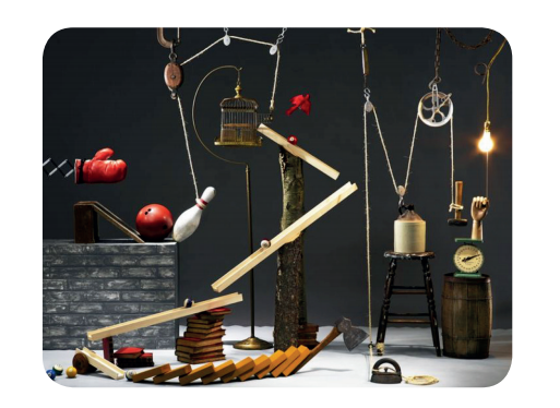
The construction of the Rube Goldberg machines does not require knowledge of the principles of the operation of simple machines, so it is an interesting idea how to make the science and technology education at primary school more interesting and challenging. The machines can be built intuitively, but also thoughtfully, based on a predetermined plan. The second option is more interesting for the development of science and technology literacy, especially if the pupil tends to explain his suggestions.